WESTPORT TERMINAL RR |
New |
[How to scratch build turnouts] and [crossings] [Manual thrown Peco turnouts] [switch stands] [Movable magnets] [DCC] [beacon light] [CB&Q 173] [RS-1 and weathering] [tender pick up 0-8-0] [ Track Cleaning Transfer Caboose ] [ Signal Bridge ] [Operation] [Way of Hopper BN 25 3 84] [WT RR industries shipping & receiving] download Excel [carcards&waybills] 900kB [staging] [Harbor District] [Plywood District] [Third Street Industrial District] [track scale, structures] [Operating gates] [Waterfront Structures] [trestle] [Interchange Cars] [car exchange] [pass exchange] [electronic rail pass ] [ video ] |
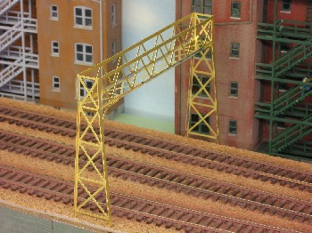
Signal bridge
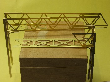
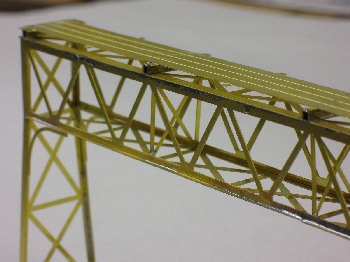
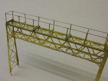
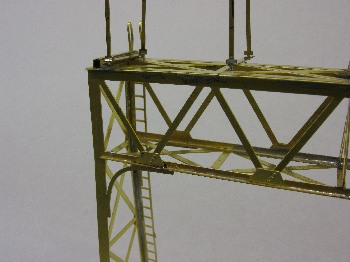
In 2004 I've bought the PRR 4 Track Signal Bridge from Alkem Scale Models. This type is similar to the type Westport Terminal RR uses. This bridge is for 4 tracks, I need a 3 Track Signal Bridge. So I had the bridge to shorten. At first I soldered the Main Truss to the Vertical Truss. For the angeled cut I followed the suggestion from my son. At the end of the first evening:
Pictures are linked to a larger view, click on them.

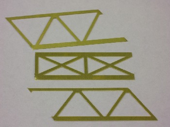
The left over parts: |
 |
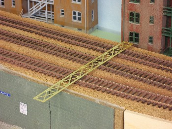
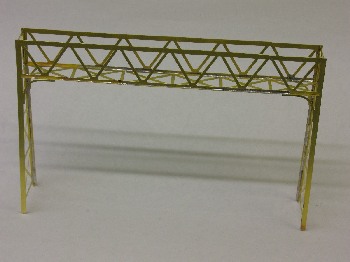
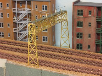
... and a first test. It will take some time until I can install the bridge, with lights!
I made the decision for a brass kit. It looks more delicate. I knew that
I had to kitbash the bridge, a commercial bridge would not suit. This is
with brass more easy. Well, twenty years ago I've scratchbuild a brass bridge
already. You can see it in my "Oldie"-video Hennen,
32 MB. This was a bridge in a curve and at grade! Thanks to small resolution,
you can't recognize not much.
This Alkem Scale Models is for 4 tracks with 13' track spacing. Well, I've
only 3 tracks. My 3 tracks have about 13' spacing. The two main tracks only
45mm (12.8' ) and the branch a little bit more!
To get strength I made the cut for the Main Truss at one side and the cut
for the Horizontal Truss at the other side. You see this in the second picture.
For soldering I followed the suggestions, no torch. This would give too
much heat at one point! I used the soldering iron from my soldering unit
sized for 400°C (750°F).
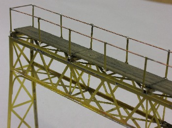
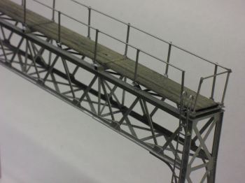
For the walkway supports I had to use my own U Channel instead. I took what
I had in similiar size.
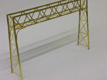
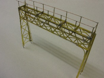
I inserted the sway braces and soldered the shortened walkway.
They suggested to substitute the etched planks as the etched planks are
too thin. And so I did. I resolderd the walkway and made my own from wood.
Therefore I made from brass strip the hand rail bases, drilled the holes.
Then I soldered a 0.02 wire to the stanchions and all together to the hand
rail bases. Each stanchion was soldered into the matching hole I've drilled.
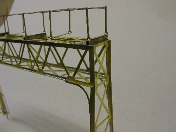
Here're the next pictures with brass and wooden deck:
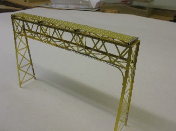
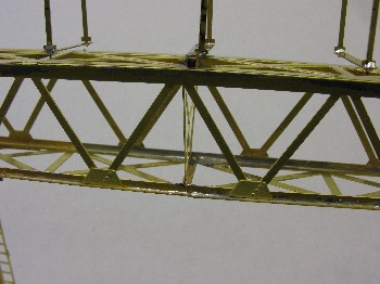
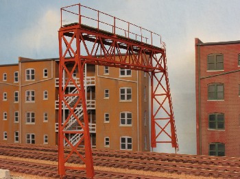
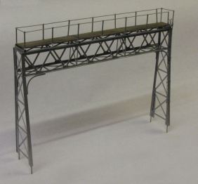
I have added the gusset plates. You have carefully to look at them to identify which goes where! Also the ladeer was not etched like in the drawing shown. So I had to improvise like I did already with the walkway. I missed the pedestals in the kit. They should be foldet and soldered, told at least the instruction. I will make them from pieces of wood. Therefore I soldered short pieces of wire at the four ends of the legs.
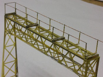
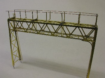
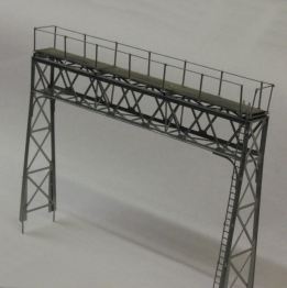
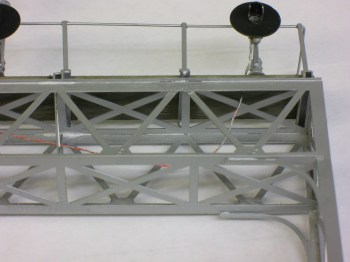
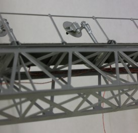
And a few close up pictures:
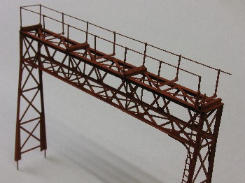
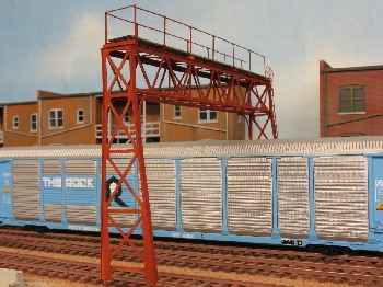
At last for this time I airbrushed the bridge with primer. Now it will
rest for a week.
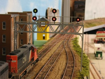
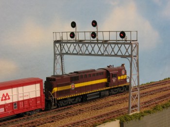
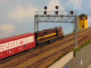
And - of course - a few trains test running:
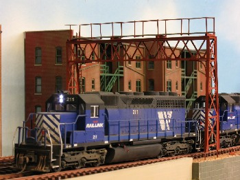
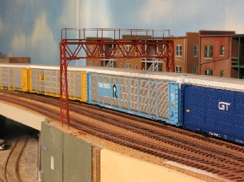
Well, the bridge was 30 minutes in the oven at 100°C (210°F). Now
I've airbrushed the next color. This color has to dry. I've airbrushed the
signals too I've got from Sunrise
Enterprises. Installing them will be the next step.
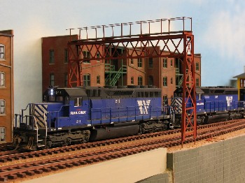
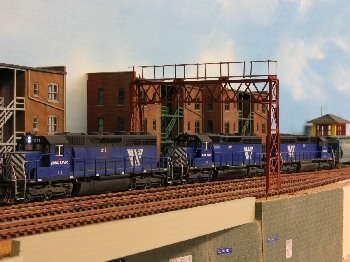
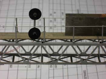
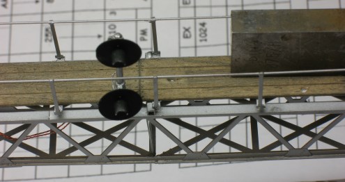
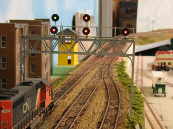
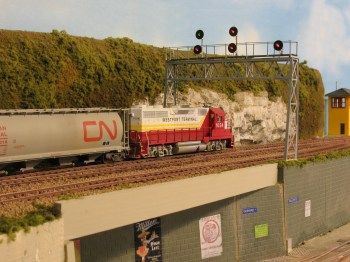
I drilled holes into the walkway and glued the signl masts with CA. But
at first I tested them. ![]() Each
target has three wires, the first signal has also six wires. I bend the
wires and glued them with CA to the structure. All wires are hidden at the
angles of the beams. Exept one wire, this represents all cables leading
down along the leg of the signal bridge. You can it notice at the big picture.
Each
target has three wires, the first signal has also six wires. I bend the
wires and glued them with CA to the structure. All wires are hidden at the
angles of the beams. Exept one wire, this represents all cables leading
down along the leg of the signal bridge. You can it notice at the big picture.
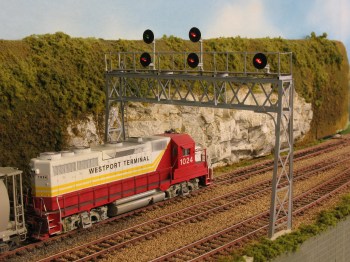
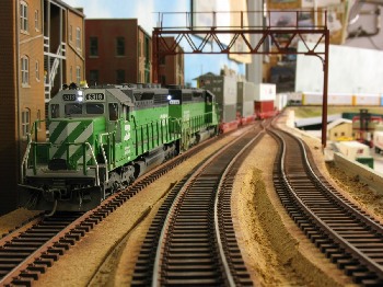
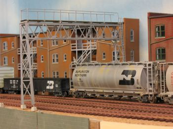
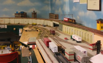
But the next step was scenery. I had to ballast the track and let grow some weeds. I soldered all wires to a tag block. Each ground wire got it's 1 kOhm resistor and a diode, to make sure: ground - minus - common.
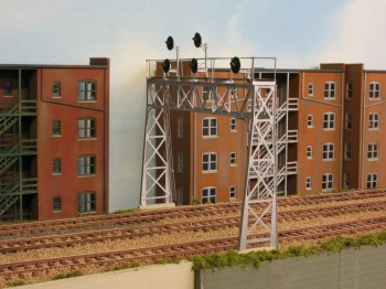
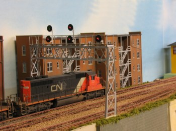
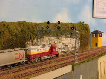
Now I've to decide which background looks better.
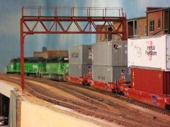
And all the Harbor District:
t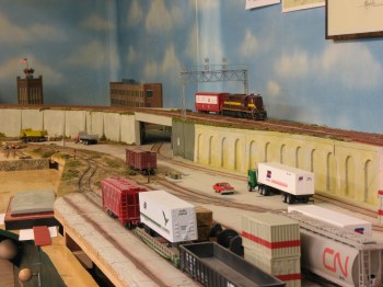
| [How to scratch build turnouts] and [crossings] [Manual thrown Peco turnouts] [switch stands] [Movable magnets] [DCC] [beacon light] [CB&Q 173] [RS-1 and weathering] [tender pick up 0-8-0] [ Track Cleaning Transfer Caboose ] [ Signal Bridge ] [Operation] [Way of Hopper BN 25 3 84] [WT RR industries shipping & receiving] download Excel [carcards&waybills] 900kB [staging] [Harbor District] [Plywood District] [Third Street Industrial District] [track scale, structures] [Operating gates] [Waterfront Structures] [trestle] [Interchange Cars] [car exchange] [pass exchange] [electronic rail pass ] [ video ] |